
Solutions · Microwave radio links
Where the fiber does not reach, the site’s traffic travels over a microwave radio link.
We design and install point-to-point (PTP) and point-to-multipoint (PTMP) microwave links that carry radio site traffic through to the network: path study, link sizing, frequency applications, antenna installation and alignment, acceptance testing with measurements, and supervision of the link in service.

What a microwave radio link is, and when it is the right choice.
Many radio sites sit where optical fiber does not reach: a tower on high ground, an isolated shelter, a technical room in a mountain area. Running fiber all the way there means excavation, crossings, and permits, with lead times and costs the project often cannot carry. A microwave link covers that distance with no civil works: two directional antennas in line of sight carry voice, data, and alarms between the site and the rest of the network. When the link goes down the site is cut off, radio voice no longer passes, equipment alarms do not reach the control room, and remote supervision stops.
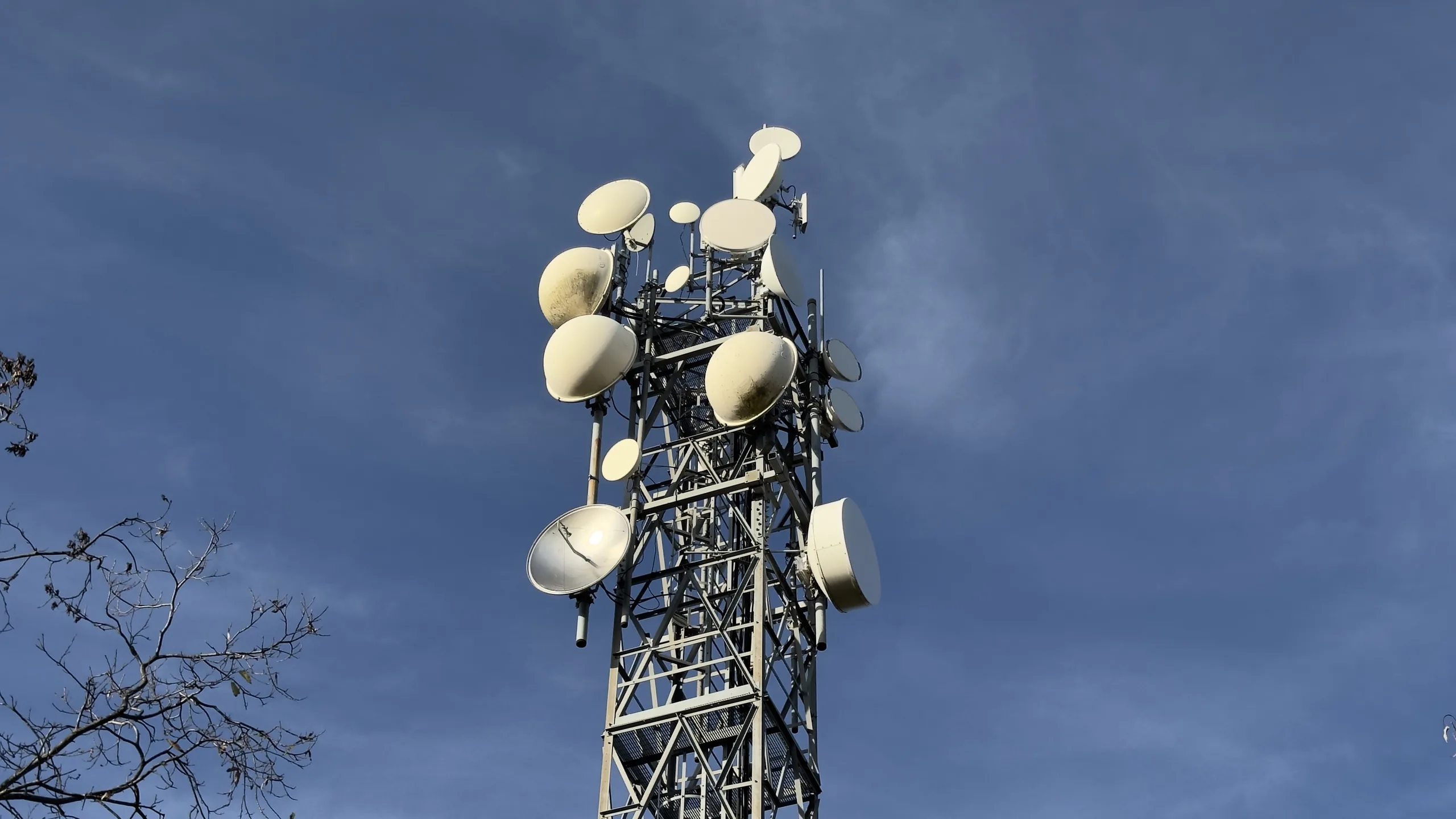
That is why we treat a microwave link as a project in its own right, not as an accessory to the site. We start from the terrain profile of the path and from a check of the line of sight between the two points, which we do on site and not only on maps. We calculate the link budget, choose the operating band, the antenna diameter, and the supports, and follow the authorization process through to the licence that permits the use of the frequencies. We install and align the antennas by reading the received level at both ends, then close with the acceptance measurements and the acceptance report.
On handover the link stays monitored in Track-TP, our supervision platform: it collects the status of the equipment and alerts our technicians when the received level deteriorates.

What makes a microwave link difficult.
What decides whether a path stays stable over the years, from the geometry of the route to the strength of the supports.
Line of sight between the two sites
A microwave link works only if the two sites are in line of sight, with no obstacles on the path. A rise in the ground, a building put up after the link entered service, or vegetation grown over the years enters the link corridor and attenuates the received signal. Line of sight has to be verified on site, not only on maps.
The link margin
The link has to be sized with a margin that accounts for heavy rain and the other path losses. A link calculated to the limit works in fine weather and loses quality when the weather turns: the margin depends on the path length, the operating band, the antenna diameter, and the power of the equipment.
Alignment and supports
Microwave link antennas are directional: a mast that sways in the wind, or a tower that settles over time, shifts the aim and brings the received level down. What counts is the stiffness of the support at the installation height, the sizing of the brackets, and locking the adjustment screws once alignment is finished.
How a microwave radio link is built.
One path seen in section: the radio site at one end, the network node on high ground at the other, and the point-to-multipoint paths that reach the remote sites from the node.
- Point-to-point path (PTP)
- The solid blue line is the point-to-point link: two directional antennas aimed at each other carry the radio site’s traffic through to the network node.
- Point-to-multipoint paths (PTMP)
- The dashed lines are the point-to-multipoint paths: from the network node a single unit serves several remote sites located in the same area.
- Corridor clear of obstacles
- The first Fresnel zone around the link has to stay clear: high ground, buildings, and vegetation that enter it attenuate the received signal.
- Sites in line of sight
- The two sites have to be in line of sight, with no obstacles on the path. Where there is no line of sight, the link is split into two hops with an intermediate repeater site.
What building a radio link involves.
The work we carry out on every link and what each stage covers, from the path study to supervision of the link in service.
Path study and terrain profile
- Choice of the two sites and of the antenna installation height on each support
- Terrain profile of the path derived from the ground mapping
- Check of the obstacles on the path: high ground, buildings, vegetation, and other supports
- Verification that the first Fresnel zone stays clear along the whole length of the link
- Alternative paths and intermediate repeater sites when the direct link is not clear
Site survey at both ends
- Visual check of mutual line of sight from the points where the antennas will go
- Survey of the coordinates, heights, and azimuth of each site
- Space available on the mast or tower, and antennas already installed on the same support
- Space in the technical room or the shelter, rack position, and cable routes
- A spectrum analyzer survey of the signals already present at the site
Link sizing
- Link budget with the transmit powers, the antenna gains, and the path losses
- Capacity sized on the traffic to be carried: radio voice, supervision data, and alarms
- Choice of the operating band based on the path length and the frequencies available in the area
- Choice of antenna diameter, polarization, and design margin for rain attenuation
- A point-to-point (PTP) configuration between two sites, or point-to-multipoint (PTMP) when one central site serves several remote sites
Frequencies and authorizations
- Check of channel availability and of compatibility with the installations already operating in the area
- Technical documentation to support the application: coordinates, heights, azimuth, and equipment characteristics
- Submission of the application and dealings with the competent authority through to the licence
- Renewals and amendments when the equipment, the installation heights, or the operating band change
Supports, structures, and cabling
- Masts, towers, and brackets: foundations, anchors, and a check of the tightening torques
- Verification of the stiffness of the support at the height planned for the antenna
- Mounting brackets sized for the antenna diameter and the wind load
- Route and fixing of the cables between the outdoor unit on the support and the equipment in the rack
- Cable entries, ducts, and watertightness at the crossings into the technical room or the shelter
Antenna mounting and alignment
- Antennas mounted at the height and azimuth the design specifies
- Alignment at both ends of the path, reading the received level
- Verification that the aim is on the main lobe and not on a side lobe
- Final tightening and locking of the adjustment screws once alignment is finished
- Sealing of the connectors and joints exposed to the weather
Equipment, power supply, and earthing
- Equipment mounted in the rack of the technical room or the shelter
- Dedicated power lines, protection devices, and uninterruptible power supplies with buffer batteries
- Bonding of equipment, supports, and antennas to the earthing system
- Surge arresters on the signal lines and on the power lines
- A functional test of the link running without mains power
Acceptance testing, supervision, and maintenance
- Measurement of the received level at both ends and comparison with the value calculated in the design
- A traffic test on the link and verification of service continuity
- An acceptance report with the values measured, and final documentation updated to the installation as built
- Supervision of the link in Track-TP, with notifications by email, WhatsApp, and Telegram
- Scheduled maintenance visits: levels, antenna alignment, state of the connectors and of the power supply
Frequently asked questions.
The questions we are asked most often about this type of system.
What is the difference between a point-to-point (PtP) and a point-to-multipoint (PtMP) radio link?
The difference is the number of sites connected. A point-to-point link joins two sites only, with directional antennas aimed at each other: the entire data bandwidth is dedicated to that link. A point-to-multipoint link serves several outlying sites from a single central antenna, and those sites share the available data bandwidth. Point-to-point is the better choice when you need the full capacity on one path, for example the backbone link of a tunnel; point-to-multipoint when the sites to reach are scattered and each one moves little traffic, such as sensors and low-resolution cameras distributed along a route.
Is a microwave radio link a better option than laying optical fiber?
It depends on what lies between the two sites. If the route calls for excavation, road or railway crossings, and agreements with landowners, a radio link is generally built in less time and at lower cost, because it involves no civil works. If a free duct already runs to the site, on the other hand, fiber remains the simpler choice and needs no frequency application. The two options are compared on the specific route, and they are not necessarily alternatives: on many installations the radio link is built as a backup for the fiber, so the site stays reachable even when the cable is cut.
Do you need an authorization to use a microwave radio link?
Yes. The frequencies of a microwave link are not licence-exempt: they have to be authorized by the competent authority before the link enters service, and the authorization has to be updated when the equipment, the antenna heights, or the operating band change. The application is submitted with the technical data of the link: coordinates of the two sites, heights and azimuth of the antennas, power and characteristics of the equipment. Before submitting it, we check that the channel is available in the area and compatible with the installations already in service. Teleproject handles the whole application on the customer’s behalf.
What distance can a microwave radio link cover?
There is no single distance that fits every link. Range depends on the operating band, the antenna diameter, the power of the equipment, and above all on the terrain profile between the two sites: a short path with a rise in the middle is harder than a long path in clear line of sight. The practical constraint is line of sight between the two points: where it is missing, the link is split into two hops with an intermediate repeater site. The usable distance is established with the terrain profile of the path and with the link budget, which also accounts for rain attenuation.
Can a radio link be installed on a tower that already carries other antennas?
Yes, that is the most frequent situation, but two things have to be checked before mounting. The first is the strength of the support: a microwave antenna adds weight and wind-exposed area, so the tower has to take the load at the planned height and must not sway enough to shift the aim. The second is coexistence with the installations already present: during the site survey we measure the active signals at the site with a spectrum analyzer, to rule out mutual interference between the new link and the existing antennas.
Request a proposal for a microwave radio link.
For every project we provide a tailored technical and commercial proposal based on your requirements — feasibility analysis, RF coverage study, and intervention planning.